中文版
中文版 English
 +86-(0)576-84025725
Product drawing design guide
Advice for assembly product and mould design
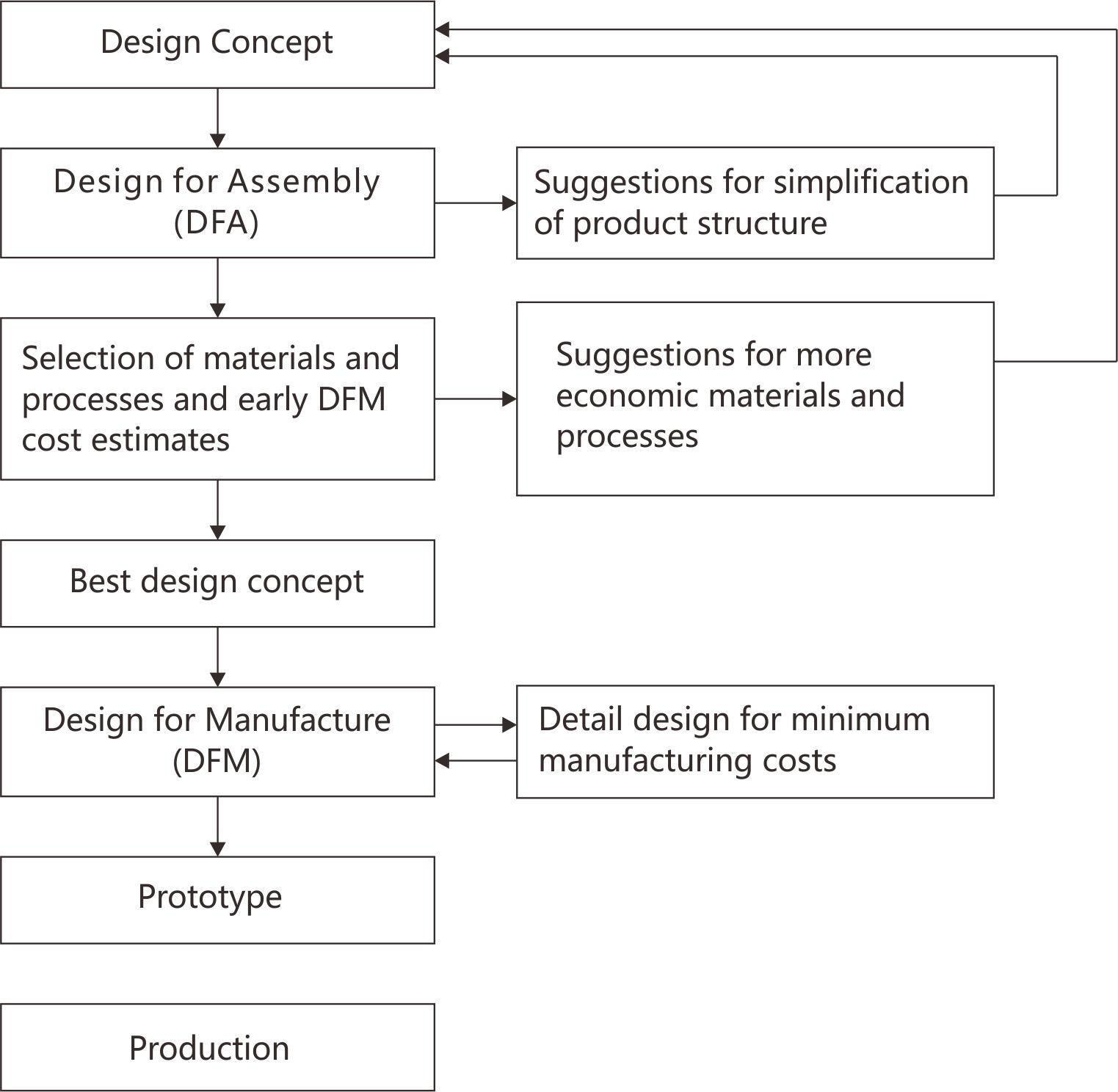
What is product design for manufacture and assembly ?
1. Manufacture refers to the manufacturing of the individual component parts of a product or assembly.
2. Assemble refers to the addition or joining of parts to form the completed product.
This means for the purpose of assembly will not be considered a manufacturing processes in the same sense that machining, molding , etc., are manufacturing process.
Thus, design for manufacture and assembly (DFMA) is a combination of design for assembly (DFA) and design for manufacture (DFM)
product design for manufacture and assembly guide structure:
Product drawing
Although it is the responsibility of the customer to provide a fully dimensioned and approved product drawing, before doing any mold design work always check these drawing to make sure they do not contain errors or omissions.
Product drawing and mould design comment
1. Dimensions
Are they plastic (final product) or steel (mold) dimensions?
(Normally, a plastic product drawing shows the dimensions after shrinkage.)
2. Artwork/surface finish
. The artwork and surface finishes must be supplied by the customer.
3. Wall thickness
. Can product fill easily and completely as it is drawn by the customer?
. re the radii sufficient to help filling or are there any pinch points?
. Plastic must always flow from thick to thin.
4. Drafts
Question any negative or no draft and determine if the product can be ejected.
. Air ejection requires a minimum of 1° draft, but better 1.75° or more. ?
. Product drawings must show all drafts and mismatches.
5. All Geometry defined? 、
. Make sure that all radii, angles, etc. are defined by the customer. Note areas where a minimum radius of 0,08 mm is required.
6. Parting line/split line
. The locations of the parting line and all split lines must be shown on the product drawing and approved by the customer.
. Printing areas and/or cosmetic requirements for the product may require that these locations be reconsidered and moved.
. The customer must approve all final parting line and split linelocations.
7. Sink marks
. Notify the customer of areas were sinks may occur (thick sections or
ribs) and get his approval.
8. Gate location and gate vestige
. Determine if the gate vestige will be an issue. If the bottom of the container is flat or the customer will print over the gate, the gate position could become a problem. A recessed gate should be considered in these cases.
It is recommended to always use a dimple! A dimple is used to prevent
gate cracking in PP and PS parts. It also aids filling of the products.
9. Shrinkage/warpage
. Shrinkage data must be provided by the customer.
. Avoid any flat bottoms. A domed bottom will prevent warpage. If you cannot dome the bottom, suggest ribs or a foot to aid in stability.
. ALWAYS question possible warpage in rectangular products. Intensive cooling in strategic areas and thicker walls can reduce the problem.
10. Ribs
. Any ribs must be shown in plan, top and side view. The rib must have draft in every direction. The rib should be no thinner than 0.5 mm and be no greater than 75% of the nominal wall section to avoid sinks.